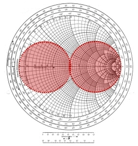

The u nit circle diagram corresponds to an unmatched circuit with total reflection | | = 1. The center of the diagram corresponds to a matched circuit with no reflect signal ( = 0). Thus, any circle with the center coinciding with the center of the diagram contains equal values of the modulus of the reflection coefficient.


The angle is calculated counterclockwise.īasic properties of the Smith chart (See figure below ): The length of this vector is equal to the response amplitude, and the angle between the vector and the positive part of the real coordinate axis is equal to the phase of the response.


 0 kommentar(er)
